Embedded WebAssembly on a D1 Mini with WASM3
With WebAssembly (WASM) emerging outside the browser, several options for embedded WASM have begun to mature. One such platform is WASM3. It positions itself as "The fastest WebAssembly interpreter, and the most universal runtime" with cross-platform support across a range of architectures and operating systems. It's able to achieve this because it takes an interpreted approach as opposed to using a Just In Time compiler. The documentation explains the motivation as
In many situations, speed is not the main concern. Runtime executable size, memory usage, startup latency can be improved with the interpreter approach. Portability and security are much easier to achieve and maintain. Additionally, development impedance is much lower. A simple library like Wasm3 is easy to compile and integrate into an existing project. (Wasm3 builds in a just few seconds). Finally, on some platforms (i.e. iOS and WebAssembly itself) you can't generate executable code pages in runtime, so JIT is unavailable.
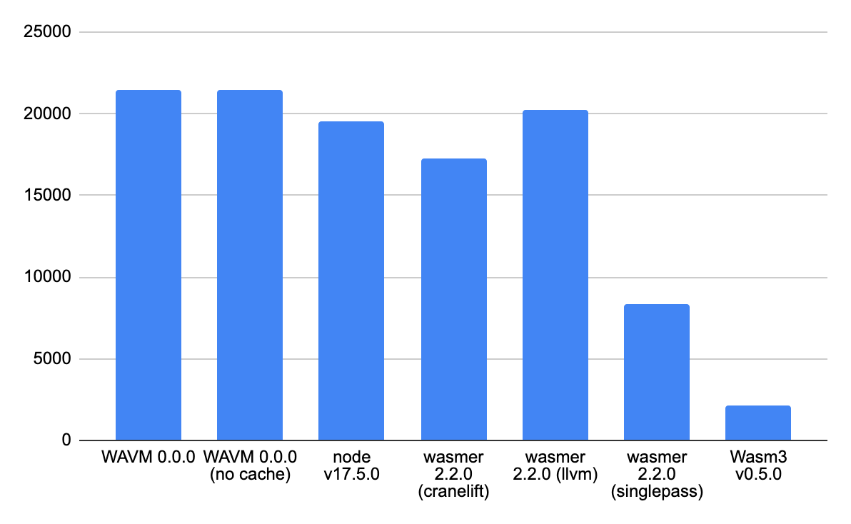
It has no dependencies and is written in very portable C making it an excellent solution for embedding in environments like iOS that don't support JIT compilation. This approach does come with a performance penalty which is visible when benchmarked against other runtimes.
However, this tradeoff may be acceptable depending on your use case. It may not be suitable for systems that have real-time requirements but may be fine for day-to-day IoT systems.
Having an on-system interpreter also opens up some interesting architectural possibilities. For example,
- Since your business logic is contained inside of a WASM module, you have clearly defined interface boundaries that you can test without depending on the target system.
- WASM runtimes exist on multiple systems there are more opportunities for shared code across platforms and domains.
Focusing specifically on the embedded space, since the module is interpreted at runtime, it may be dynamically loaded from a filesystem. Let's explore this use case.
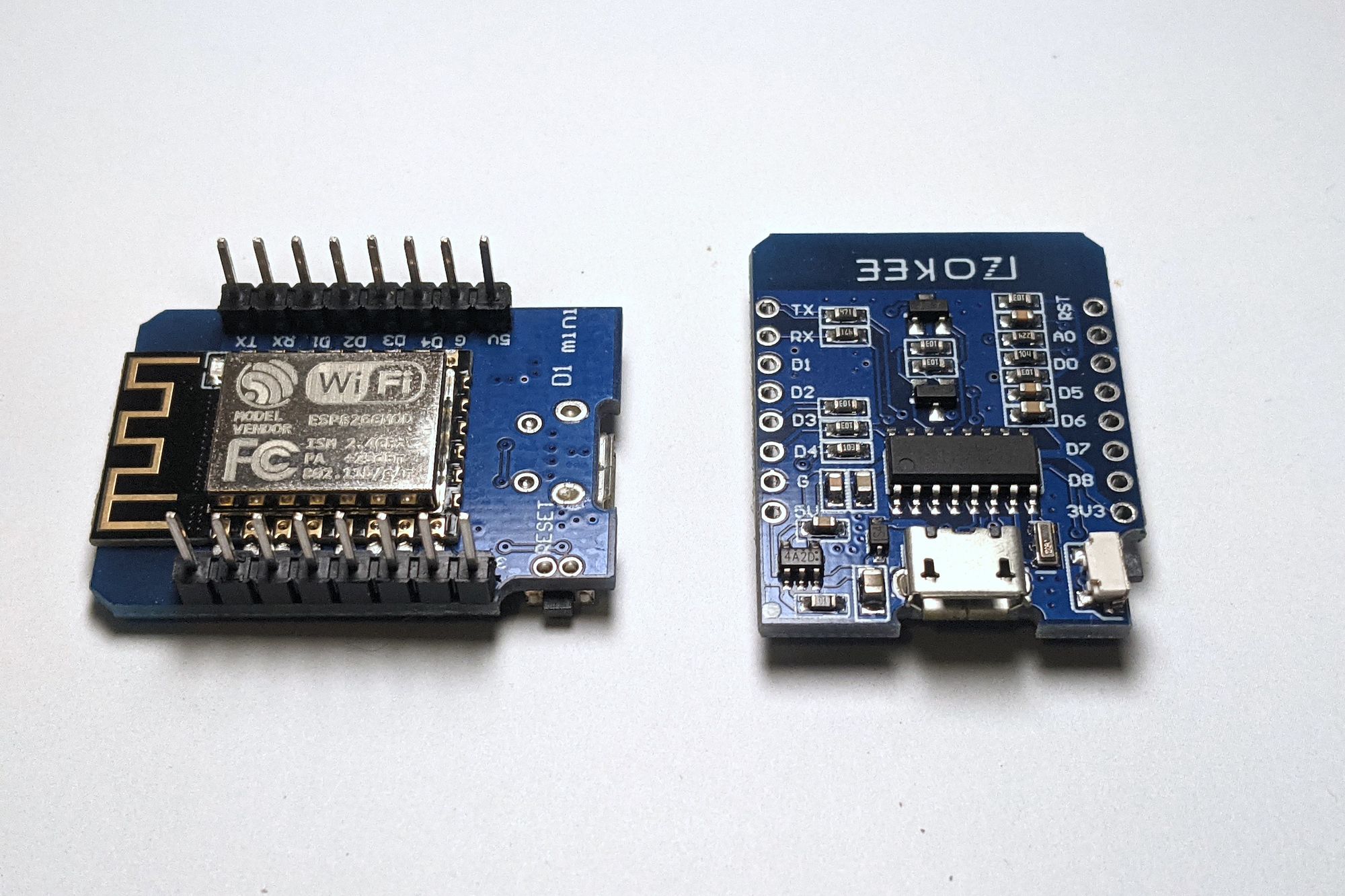
The D1 Mini
To experiment, we need to pick a platform and I've chosen the Wemos D1 Mini Lite. It's a small and inexpensive ESP8266-based WiFi board that is Arduino compatible. It's a versatile piece of hardware that's very easy to work with. It is my go-to "Arduino but with WiFi" device and a great way to add wireless connectivity to any project.
The D1 Mini Lite's specifications are listed as
| Microcontroller | ESP8266 |
| Digital I/O Pins | 11 |
| Analog I/O Pins | 1 |
| Clock Speed | 80/160MHz |
| Flash | 4MB |
| User data RAM (ESP8266) | 80KiB |
| Instruction RAM (ESP8266) | 32KiB |
While these might not look like a lot when compared with modern desktop devices, for an embedded system these specs are relatively impressive.
Setup
To get started, I'll be using the awesome PlatformIO IDE. Starting with a platformio.ini manifest which includes configuration options for the environment.
[env:d1_mini_lite]
platform = espressif8266
board = d1_mini_lite
framework = arduino
board_build.filesystem = littlefs
monitor_speed = 115200
lib_deps =
	wasm3/Wasm3@^0.5.0
	ayushsharma82/AsyncElegantOTA@^2.2.6
	me-no-dev/ESPAsyncTCP@^1.2.2
	me-no-dev/ESP Async WebServer@^1.2.3
Here I'm using the Arduino framework, littlefs file system, and AsyncElegantOTA which will help us run Over-The-Air (OTA) filesystem updates through an embedded webserver.
In the main.cpp file, I'm starting off with a couple of utility functions which will be called in setup.
void startSerial()
{
    Serial.begin(115200);
    while (!Serial)
    {
    }
    // Blank line for nicer output
    Serial.println("");
}
startSerial initializes serial logging which we can view using the PlatformIO serial monitor. The baud rate should match the monitor_speed specified in the manifest.
const char *ssid = "Your WiFi SSID";
const char *password = "Your WiFI Password";

void startWifi()
{
    WiFi.mode(WIFI_STA);
    WiFi.begin(ssid, password);
    // Wait for connection
    while (WiFi.status() != WL_CONNECTED)
    {
       delay(500);
       Serial.print(".");
    }
    Serial.println("");
    Serial.print("Connected to ");
    Serial.println(ssid);
    Serial.print("IP address: ");
    Serial.println(WiFi.localIP());
}
startWifi initializes the onboard Esp8266 WiFi module, starts a connection to the provided WiFi Access Point (AP) then logs the IP Address that it has been assigned. We'll need this to interact with a web server that we'll be starting.
// Relevant include
// #include <AsyncElegantOTA.h>

AsyncWebServer server(80);

void startWebServer()
{
    server.on("/", HTTP_GET, [](AsyncWebServerRequest *request)
             { request->send(200, "text/plain", "OK!"); });
    // Start ElegantOTA
    AsyncElegantOTA.begin(&server);
    server.begin();
}
startWebServer creates an HTTP server using AsyncWebServer. It adds 2 routes. The first returns static text which we can use to verify that the server is working correctly. We can validate this by visiting the IP address we obtained earlier. The second is on /update which is added by AsyncElegantOTA. It provides a minimal web UI that we'll use to flash new filesystem images.
Implementing the interpreter
To run WASM modules, a WASM3 environment needs to be created for the interpreter
#define WASM_STACK_SIZE 1024
#define WASM_MEMORY_LIMIT 4096

M3Result result = m3Err_none;
IM3Environment env = m3_NewEnvironment();
IM3Runtime runtime = m3_NewRuntime(env, WASM_STACK_SIZE, NULL);
runtime->memoryLimit = WASM_MEMORY_LIMIT;
The next step is to read the WASM module from the filesystem into a uint8_t buffer.
File file = LittleFS.open("/firmware.wasm", "r");
size_t s = file.size();

uint8_t buf[s];
file.read(buf, s);
Then parse the module using the environment.
IM3Module module;
result = m3_ParseModule(env, &module, buf, s);
if (result)
{
    Serial.println("Failed to parse module");
    Serial.println(result);
}

result = m3_LoadModule(runtime, module);
if (result)
{
    Serial.println("Failed to load module");
    Serial.println(result);
}
Now we can shift our focus to providing binding functions to the runtime. These are functions that will be invoked by the module. In this example, we'll focus on 3 functions that are needed for a simple blink sketch.
pinModeto set the LED as an outputdigitalWriteto turn the LED off and on againdelayto pause execution on the MCU
To prepare the needed binding functions, WASM3 declares macros to help simplify the process.
-
m3ApiRawFunctionwhich accepts a name as an argument and generates a function signature expected by the runtime. m3ApiGetArgThis is used to bind arguments passed to binding functions to variables that we can use within the binding function.m3ApiReturnThis is used to specify the return type ofm3ApiSuccessThis is used to notify the runtime that a void function completed successfully
To generate a binding for pinMode we can use m3ApiRawFunction
m3ApiRawFunction(m3_arduino_pinMode)
{
    // Semi colons here aren't required since these are macros
    // but my auto formatter doesn't format correctly without them
    m3ApiGetArg(uint32_t, pin);
    m3ApiGetArg(uint32_t, mode);

    pinMode(pin, mode);

    m3ApiSuccess();
}
m3ApiGetArg allows us to get access to parameters that are passed to the host runtime by the WASM module. It does this positionally - meaning that the first time you call it, you get the first parameter and so on. Here we're binding the first parameter to pin and mode as unit32_t's and delegating to the pinMode declared by the Arduino API before indicating that the function has completed successfully using m3ApiSuccess.
digitalWrite and delay look very similar.
m3ApiRawFunction(m3_arduino_digitalWrite)
{
    m3ApiGetArg(uint32_t, pin);
    m3ApiGetArg(uint32_t, value);

    digitalWrite(pin, value);

    m3ApiSuccess();
}

m3ApiRawFunction(m3_arduino_delay)
{
    m3ApiGetArg(uint32_t, ms);

    delay(ms);

    m3ApiSuccess();
}
With the binding functions in place, the next step is to bind them to the parsed module instance. This is done with m3_LinkRawFunction which accepts a parsed module, module name, function name (should match the import declaration in the WASM module), a string encoded function signature, as well as a reference to a binding function. Encoded function signatures use a symbolic notation formatted as return_type(parameter_type...) where each character corresponds to a type. 6 characters that can be used in a type signature.
v: void
i: i32
I: i64
f: f32
F: f64
*: pointer (effectively i32)
Defining a signature for our pinMode binding which returns no value (void) declares 2 i32 arguments would be v(ii). With that in mind, let's move forward defining our bindings.
const char *module_name = "env";

m3_LinkRawFunction(module, module_name, "pinMode", "v(ii)", &m3_arduino_pinMode);
m3_LinkRawFunction(module, module_name, "digitalWrite", "v(ii)", &m3_arduino_digitalWrite);
m3_LinkRawFunction(module, module_name, "delay", "v(i)", &m3_arduino_delay);
Now all that's left is to call a function in the module to begin execution.
IM3Function startF;
    result = m3_FindFunction(&startF, runtime, "_start");
    if (result)
    {
        Serial.println("Failed to find function");
        Serial.println(result);
    }

    Serial.println("Running WebAssembly...");
    result = m3_CallV(startF);

    // Getting here means we've encountered an error.
    // Let's print out some debugging information
    if (result)
    {
        M3ErrorInfo info;
        m3_GetErrorInfo(runtime, &info);
        Serial.print("Error: ");
        Serial.print(result);
        Serial.print(" (");
        Serial.print(info.message);
        Serial.println(")");
        if (info.file && strlen(info.file) && info.line)
        {
            Serial.print("At ");
            Serial.print(info.file);
            Serial.print(":");
            Serial.println(info.line);
        }
    }
I'm choosing to call _start which is defined in the WASI specification for standalone binaries. This means that the generated module should export that as the beginning of the program.
We can now compile and flash the bootstrap program we've just written to the board. PlatformIO has a handy upload command to do this.
$ platformio run --target upload

Processing d1_mini_lite (platform: espressif8266; board: d1_mini_lite; framework: arduino)
--------------------------------------------------------------------------------
Verbose mode can be enabled via `-v, --verbose` option
CONFIGURATION: https://docs.platformio.org/page/boards/espressif8266/d1_mini_lite.html
PLATFORM: Espressif 8266 (3.2.0) > WeMos D1 mini Lite
HARDWARE: ESP8266 80MHz, 80KB RAM, 1MB Flash

...

RAM:   [======    ]  63.0% (used 51604 bytes from 81920 bytes)
Flash: [=======   ]  69.5% (used 665925 bytes from 958448 bytes)

...

Compressed 670080 bytes to 434926...
Writing at 0x00000000... (3 %)
Writing at 0x00004000... (7 %)

...

Writing at 0x00068000... (100 %)
Wrote 670080 bytes (434926 compressed) at 0x00000000 in 41.9 seconds (effective 128.0 kbit/s)...
Hash of data verified.

Leaving...
Hard resetting via RTS pin...
========================= [SUCCESS] Took 45.09 seconds =========================
Building our module
With the bootstrap setup, we need a WASM module to flash onto the filesystem. I've prepared a minimal blink example in Rust, however, you may choose to build this in your language of choice provided that it compiles to WASM.
extern "C" {
    #[link_name = "pinMode"]
    fn pin_mode(pin: i32, mode: i32);

    #[link_name = "digitalWrite"]
    fn digital_write(pin: i32, state: i32);

    fn delay(millis: i32);
}

#[no_mangle]
unsafe fn _start() {
    _setup();
    loop {
        _loop();
    }
}

const LED: i32 = 0x02;
const OUTPUT: i32 = 0x01;
const LOW: i32 = 0x00;
const HIGH: i32 = 0x01;

unsafe fn _setup() {
    pin_mode(LED, OUTPUT);
}

unsafe fn _loop() {
    digital_write(LED, LOW);
    delay(300);
    digital_write(LED, HIGH);
    delay(300);
}
This imports the pinMode, digitalWrite and delay functions that we described earlier and exports _start which is the entry point of the program.
I'm compiling this with the following flags but depending on your use case and toolchain you may want to adjust as needed.
RUSTFLAGS='-C opt-level=z -C linker-plugin-lto -C link-arg=-zstack-size=4096 -C link-arg=--initial-memory=65536 -C link-arg=--max-memory=65536' cargo build --release --target wasm32-unknown-unknownopt-level=z and linker-plugin-lto help to keep the size of the compiled module down while the other flags set the maximum amount of memory to 1 page.
Flashing the filesystem
To build a filesystem image, PlatformIO requires that the image content be placed in a data folder in the root directory of the project. We can then use the buildfs command to generate a *.bin image of the content to flash.
$ platformio run --target buildfs

Processing d1_mini_lite (platform: espressif8266; board: d1_mini_lite; framework: arduino)
--------------------------------------------------------------------------------

...

Building in release mode
Building file system image from 'data' directory to .pio/build/d1_mini_lite/littlefs.bin
/firmware.wasm
========================= [SUCCESS] Took 0.40 seconds =========================
Now we can flash our file system image onto the device using uploadfs
$ platformio run --target uploadfsFlashing the file system content also resets the board so once the module begins executing we should see the classic blink sketch turn the built-in LED off and on.
Looking at the logs, with the PlatformIO serial monitor we should also see the IP address that has been assigned to the device.
Connected to WirelessRouter
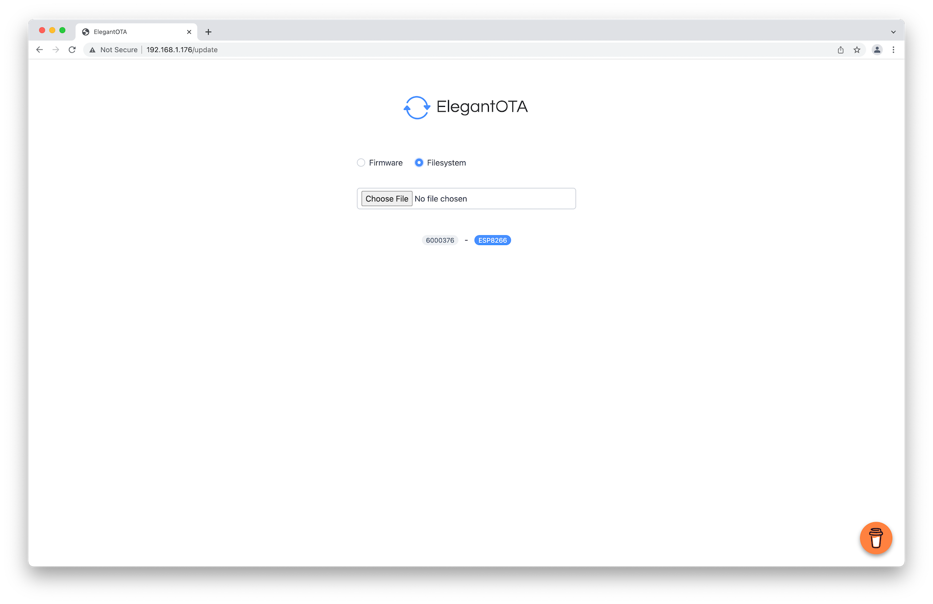
IP address: 192.168.1.176Visiting the update page in my case at http://192.168.1.176/update allows me to upload and flash a new filesystem image.
We can prepare a new filesystem image by updating our wasm source, copying the updated module to the data folder, and running the PlatformIO buildfs command to generate a *.bin file. PlatformIO conveniently places at .pio/build/d1_mini_lite/littlefs.bin after building a new image.
Conclusion
I think being able to run WebAssembly modules on embedded devices is exciting and really captures the flexibility that WASM as a compilation target offers. In this example, we've explored interpreting a WASM module hosted on a filesystem on the Wemos D1 Mini as well as an avenue for updating the module through a webserver hosted on the system. This may not be the best or most convenient way to do this but I hope it at least shows off some of WASM3's potential in the embedded space. I'm excited to see how the WASM ecosystem grows in the embedded space as well as the fun solutions that emerge in the future.