Getting into Embedded Systems

So it looks like i'm going to be going a little bit into the world of embedded device programming. Which is pretty different from what I consider to be your run of the mill software development. For starters, instead of the common 500 Gigabytes (GB) of hard drive storage in most PCs these days, the board i'll be playing with has got a whopping 16 Kilobytes[1] (KB) of flash storage (The header image on this post is about 50kb+... just to give you some context).
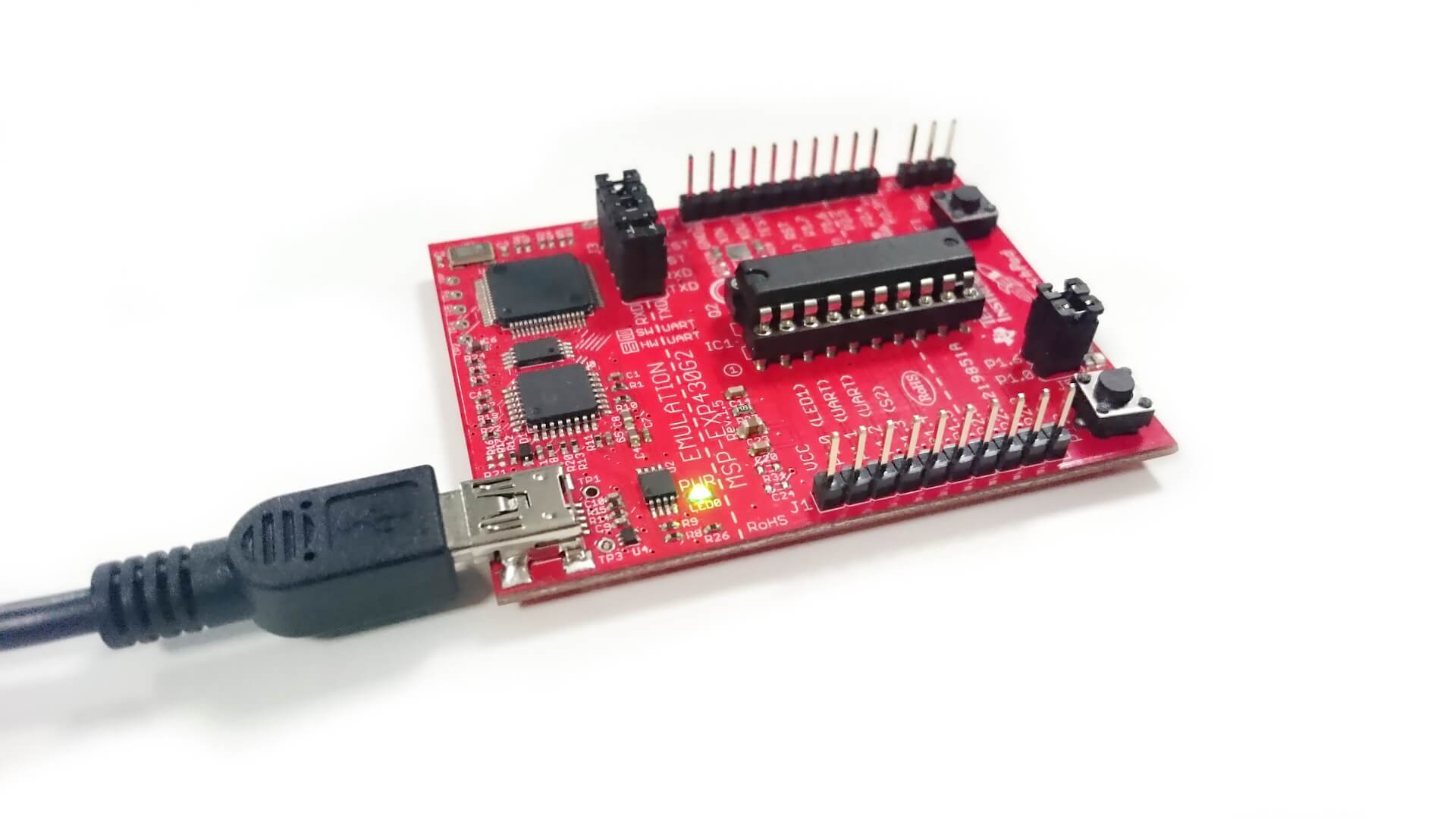
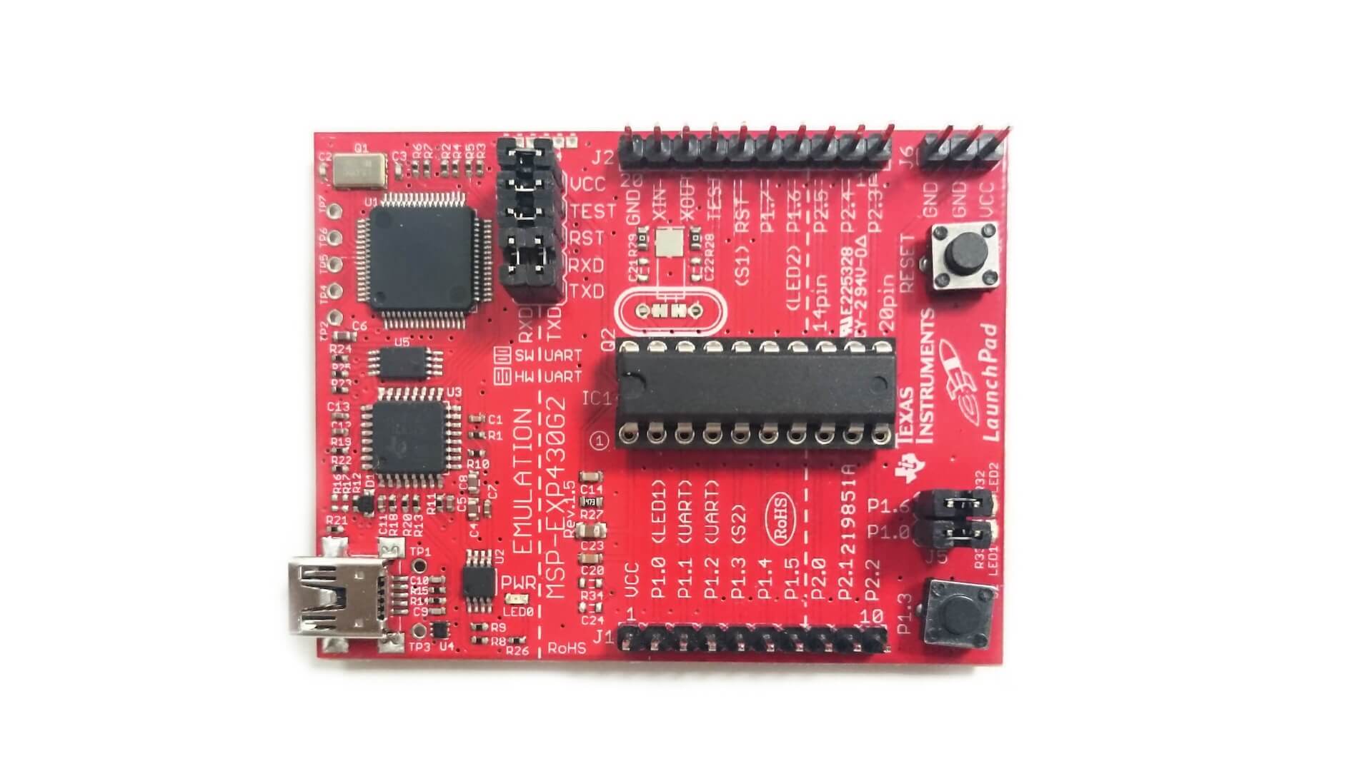
Here we have the MSP430 Micro Controller Unit (MCU) resting comfortably on a MSP-EXP430G2 Launchpad target board. It's programmed using the Mini USB port on the left.
A quick look at the code
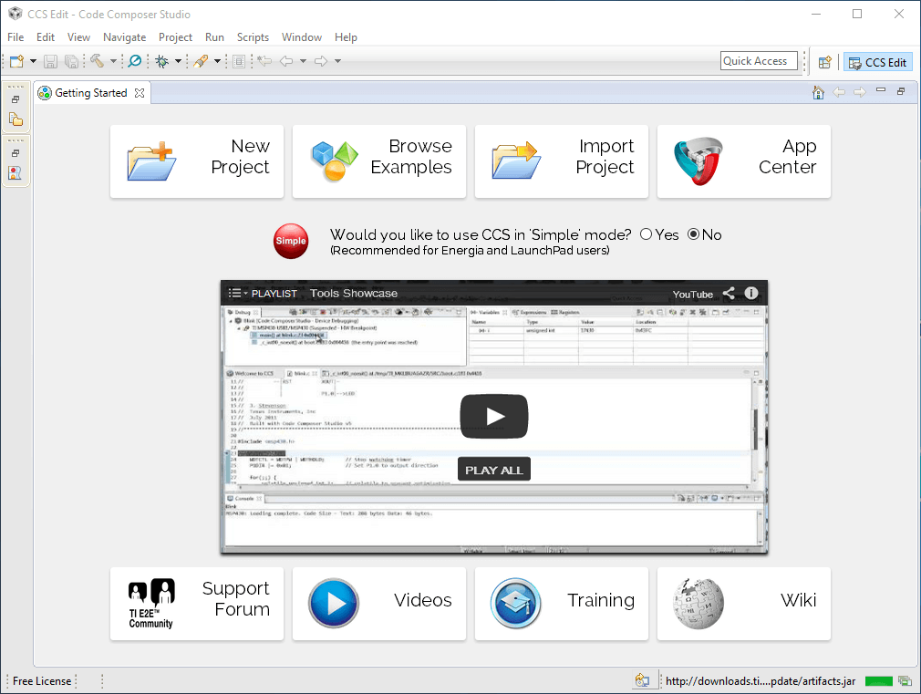
I'll be programming this bad boy using Code Composer Studio ; an Integrated Developer Environment (IDE) lovingly provided by Texas Instruments (TI). The free version will compile up to 16KB of code for the MSP430 using the TI compiler[1:1].
The microprocessor is programmed using the C programming language along with the msp430g2553 header file. One of the features i'm most pleased to see is the availability of a debugger which is useful for watching the code as it executes (I'm looking forward to getting my hands on that).
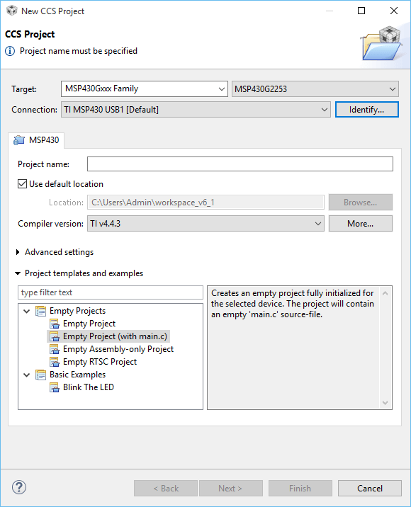
Getting started couldn't be easier, you create a new project and select your target device in the new project wizard.
Next you just write your code and click the debug button (or push F11) to compile and upload the program. Here is a simple program that blinks a Light Emitting Diode (LED) on the board.
#include  <msp430g2553.h>
unsigned int i = 0;

   // Initialize variables. This will keep
   // count of how many cycles between LED toggles

void main(void)
{
   WDTCTL = WDTPW + WDTHOLD;

   // Stop watchdog timer. This line of code is
   // needed at the beginning of most MSP430 projects.

   // This line of code turns off the watchdog timer,
   // which can reset the device after a certain period of time.
   // P1DIR is a register that configures the
   // direction (DIR) of a port pin as an output or an input.

   P1DIR |= 0x01;

   // To set a specific pin as output or input, we write
   // a '1' or '0' on the appropriate bit of the register.

   // P1DIR = <PIN7><PIN6><PIN5><PIN4><PIN3><PIN2><PIN1><PIN0>

   // Since we want to blink the on-board red LED, we want
   // to set the direction of Port 1, Pin 0 (P1.0) as an output

   // We do that by writing a 1 on the PIN0 bit of the P1DIR register
   // P1DIR = <PIN7><PIN6><PIN5><PIN4><PIN3><PIN2><PIN1><PIN0>
   // P1DIR = 0000 0001
   // P1DIR = 0x01     <-- this is the hexadecimal conversion of 0000 0001

   for (;;)

   // This empty for-loop will cause the lines of code within to loop infinitely

       {

           P1OUT ^= 0x01;

   // Toggle P1.0 using exclusive-OR operation (^=)

   // P1OUT is another register which holds the status of the LED.
   // '1' specifies that it's ON or HIGH, while '0' specifies that it's OFF or LOW
   // Since our LED is tied to P1.0, we will toggle the 0 bit of the P1OUT register

           for(i=0; i< 10000; i++);

   // Delay between LED toggles. This for-loop will run until the condition is met.
   //In this case, it will loop until the variable i increments to 20000.
       }
   }
I'll be playing around with this over the next couple of weeks so expect a few posts on my thoughts and experience using it.