Programming an Atmega32 using an Arduino
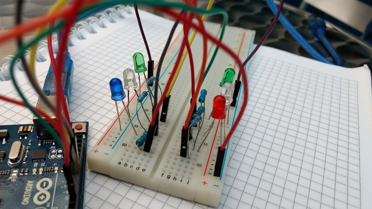
I recently revisited a project I tried to do about 4 years ago. I had bought myself an Atmega32 IC hoping to learn how to work with microcontrollers at a lower level than the standard Arduino offering. At the time, it easily went over my head; The data sheets were incredibly complex, and I couldn't really follow what I needed to actually get code onto the IC. Now armed with a few more years of experience under my belt, I decided to give this another go.
We will be using the Arduino as a programmer. Not the native FTDI interface (an FT232 on some boards and an Atmega16 on newer models).
This means that we need to configure our Arduino as an in-system programmer before we can continue. Thankfully, there's an example program; ArduinoISP, readily available in the examples.
With that out of the way, we can now begin by looking up the datasheet for the Atmega32 for the IC's pinout.
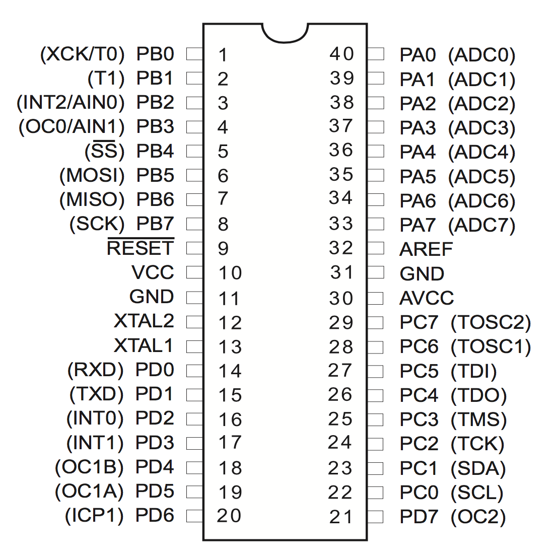
The pins that we are interested in are,
- GND - Ground
- VCC - IC power-supply pin
- RESET
- SCK - Serial clock
- MISO - Master In Slave Out
- MOSI - Master Out Slave In
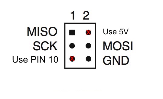
Now we need to connect this to the appropriate pins on the Arduino. The Arduino documentation recommends that you use its digital pins located on the expansion header in this configuration,
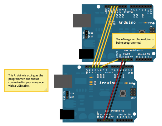
However looking at the Arduino schematic, these are simply routed through the regular SPI pins.
For this reason, if you have an SPI header on your board, you can go ahead and use those.
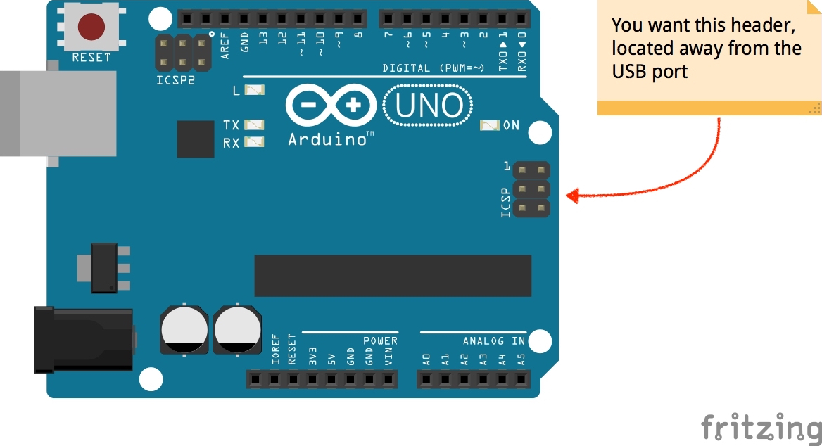
There are a few caveats, however.
-
Pin 10 is used as the reset pin, and this does not go through the SPI header.
-
VCC on the SPI may not be reliable on some boards, it's best to use the 5V power supply on the expansion header.
So these are the pins you should be connecting.
Getting the software is pretty easy. You'll need
- avr-libc
- avr-gcc
- avrdude
Windows users should obtain these via the WinAVR package. These libs are available on mac, through the Crosspack library. Linux users should look to their favorite package manager for the lib.
At this point you want to check your connection to avrdude to make sure that you are actually able to program the board, you can do this using
$ sudo avrdude -c arduino -p atmega32
The -c option allows you to specify the programmer while the -p option allows you to specify the part number being programmed. Refer to the avrdude cli options page for more.
Next, we need to compile our code. It could be whatever you plan to upload however here's a simple blinky LED sample for reference.
 #include<avr/io.h>
 #include<util/delay.h>

 int main(void)
 {
    DDRC=0xFF;      // PORTC declared as output
    while(1)
    {
        PORTC = 0xFF; //Turns ON All LEDs
        _delay_ms(1000);    // one second delay
        PORTC= 0x00; //Turns OFF All LEDs
        _delay_ms(1000);
    }
}
We can compile this using avr-gcc.
$ avr-gcc -Wall -Os -DF_CPU=8000000 -mmcu=atmega32 -c main.c -o main.o
$ avr-gcc -o main.elf main.o
The -Wall and -Os are standard options we provide to GCC when compiling C code. However, the option for -DF_CPU sets the F_CPU option. This allows you to tell the compiler the expected clock frequency of your device. The -mmcu option allows you to set the MCU that you are targetting. Next, we invoke avr-gcc again to package our object into an *.elf file.
Now we have a nice elf file, however, we're not done yet. The next step would be to generate a *.hex file we can upload to the board.
avr-objcopy -j .text -j .data -O ihex main.elf main.hex
The -j option here says to copy a section from the elf file while generating the hex file. We specifically want the text and data sections which contain the executable data as well as globally defined variables. -O specifies the output format.
At this point, we have a hex file and are ready to flash it onto the IC. We can again defer to avrdude for this task
avrdude -c arduino -p atmega32 -P PORT -b 19200 -U flash:w:main.hex
The -P command specifies the port. Locating this might be different depending on your operating system. However, you should generally be able to find this in the Arduino IDE. - specifies the baud rate to use when flashing. -U is used to specify a memory operation to be done on the IC. Following it up with flash tells it to operate ROM on the device. w indicates that we want to write to it. Finally, we tell it what *.hex file we should use.
References
- AVR Freaks. Understanding F_CPU. [online] Available at: https://www.avrfreaks.net/forum/understanding-fcpu [Accessed 2 Jun. 2019].
- Microchip. AVR Libc Reference Manual; A simple project. [online] Available at:https://www.microchip.com/webdoc/AVRLibcReferenceManual/group__demo__project_1demo_ihex.html [Accessed 2 Jun. 2019].
- Adafruit. ArduinoISP. [online] Available at: https://learn.adafAdafruit. ruit.com/arduino-tips-tricks-and-techniques/arduinoisp
- www.nongnu.org. AVR User manual - Option Descriptions. [online] Available at: https://www.nongnu.org/avrdude/user-manual/avrdude_4.html#Option-Descriptions